xnx xnx transmitter installation manual
The XNX Universal Transmitter is a versatile‚ cost-effective solution for gas detection‚ compatible with Honeywell’s extensive range of sensor technologies․ It supports HART‚ Modbus‚ and Foundation Fieldbus protocols‚ offering flexibility in system integration․ Designed for simplicity‚ the XNX simplifies installation‚ reduces costs‚ and ensures reliable performance across various industrial applications․
1․1 Product Description
The XNX Universal Transmitter is a cutting-edge‚ versatile gas detection solution designed to work seamlessly with Honeywell’s extensive range of gas sensor technologies․ It supports various sensing methods‚ including catalytic bead‚ infrared‚ and electrochemical sensors‚ making it a flexible option for detecting toxic and flammable gases․ The transmitter features a modular design‚ allowing for easy integration of optional communication boards such as HART‚ Modbus‚ and Foundation Fieldbus․ Its universal platform simplifies installation and configuration‚ reducing costs and complexity․ The XNX is ideal for both hazardous and non-hazardous areas‚ ensuring reliable performance and compliance with industry safety standards․

1․2 Key Features and Benefits
The XNX Universal Transmitter offers a range of advanced features designed to enhance performance and simplify operation․ It supports multiple communication protocols‚ including HART‚ Modbus‚ and Foundation Fieldbus‚ ensuring compatibility with various control systems․ The transmitter’s modular design allows for easy installation of option boards‚ such as relay‚ Modbus‚ or Foundation Fieldbus‚ without requiring specialized tools․ Its universal compatibility with Honeywell’s gas sensors enables flexibility in detecting toxic and flammable gases․ The large LCD display provides clear configuration and monitoring capabilities‚ while intrinsic safety certifications ensure safe operation in hazardous environments․ These features combine to deliver a reliable‚ low-maintenance solution for gas detection systems․

Installation and Mounting
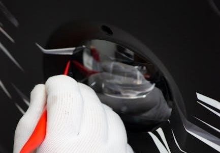
The XNX Universal Transmitter can be mounted using integral mounting tabs for flexibility․ Ensure proper grounding and use certified M25 cable glands for secure connections․
2․1 Pre-Installation Requirements
Before installing the XNX Universal Transmitter‚ ensure the power supply matches the device’s specifications (16-32 VDC for EC/mV versions‚ 18-32 VDC for others)․ Verify intrinsic safety requirements and grounding to prevent electrical hazards․ Use only certified M25 cable glands for secure connections․ Read and understand the technical manual thoroughly․ Ensure the area is non-hazardous before opening the enclosure․ Properly shield and ground the sensor for safe operation․ Confirm compatibility with connected devices and systems to ensure seamless integration and reliable performance․
2․2 Mounting Options and Considerations
The XNX Universal Transmitter offers versatile mounting options‚ including wall‚ pole‚ or DIN rail configurations‚ ensuring adaptability to various installation environments․ Use the integral mounting tabs for secure placement‚ ensuring the transmitter is stable and protected from vibration or movement․ Consider environmental factors such as temperature‚ humidity‚ and exposure to hazardous substances when selecting a location․ Ensure the area is accessible for maintenance while being protected from direct sunlight or extreme weather conditions․ Proper grounding is essential for intrinsic safety compliance․ Consult local regulations and standards for specific mounting requirements in hazardous areas;
2․3 Power Supply and Wiring Basics
The XNX Universal Transmitter operates on a DC power supply‚ with voltage ranges varying by model (e․g․‚ 16-32 VDC for EC/mV versions)․ Ensure the power source matches the transmitter’s specifications to avoid damage․ Wiring must comply with local electrical standards‚ using shielded‚ armored cables to minimize noise interference․ Proper grounding is critical for intrinsic safety and electromagnetic compatibility․ Use certified cable glands and follow the manufacturer’s wiring diagrams for connections․ Avoid overloading circuits and ensure all connections are secure to prevent signal degradation․ Always power down the unit before modifying wiring to ensure safe installation and maintenance․

Wiring and Connections
The XNX Universal Transmitter supports flexible wiring configurations‚ including source‚ sink‚ or isolated outputs‚ selectable via a switch on the POD․ Use shielded cables to minimize interference and ensure proper grounding for intrinsic safety․ Follow Honeywell’s wiring diagrams for accurate connections‚ and verify compatibility with your control system․ Secure all connections to prevent signal degradation and ensure reliable communication across HART‚ Modbus‚ or Foundation Fieldbus protocols․
3․1 General Wiring Considerations
Proper wiring is essential for reliable operation of the XNX Universal Transmitter․ Use shielded‚ armored cables to minimize electromagnetic interference (EMI) and ensure signal integrity․ Ground the transmitter and sensor correctly to maintain intrinsic safety and prevent noise interference․ Verify the power supply voltage matches the transmitter’s requirements‚ typically 16-32 VDC‚ depending on the model․ Avoid voltage drops in long cable runs to ensure accurate sensor performance․ Follow Honeywell’s recommended wiring practices and consult the technical manual for specific guidelines․ Ensure all connections are secure and comply with international safety standards for hazardous environments․
3․2 Wiring Schematics and Diagrams
Refer to the XNX Universal Transmitter’s technical manual for detailed wiring schematics and diagrams․ The transmitter supports configurations as a current source‚ sink‚ or isolated output‚ selectable via a switch on the POD․ Ensure proper grounding to maintain intrinsic safety and prevent electrical noise․ Use shielded cables to minimize EMI interference․ Wiring diagrams vary based on the selected communication protocol (HART‚ Modbus‚ or Foundation Fieldbus)․ Verify connections to terminals TB1‚ TB2‚ and TB3 for power‚ sensor inputs‚ and communication․ Always follow the recommended wiring practices to ensure compliance with international safety standards and optimal performance in hazardous environments․
3․3 Configuring Source‚ Sink‚ or Isolated Outputs
The XNX Universal Transmitter allows configuration as a current source‚ sink‚ or isolated output to adapt to different control systems․ The output type is selected using a switch located on the back of the POD․ Source mode provides a 4-20mA output driven by the transmitter‚ while sink mode pulls current from the control system․ Isolated mode ensures no direct electrical connection between the transmitter and the control system‚ enhancing safety in hazardous environments․ Proper configuration ensures compatibility with the connected system and maintains intrinsic safety․ Refer to the technical manual for specific setup instructions and to avoid electrical interference or system malfunctions․

Configuration and Calibration
This section provides a comprehensive guide for configuring and calibrating the XNX Universal Transmitter‚ ensuring accurate gas detection and reliable performance in various industrial settings․
4․1 Initial Setup and Configuration
The initial setup of the XNX Universal Transmitter involves powering up the device and navigating through its intuitive interface to configure basic settings․ Ensure the transmitter is properly grounded and connected to the power supply․ Use the menu-driven interface to set parameters such as gas type‚ measurement units‚ and alarm levels․ Configure communication protocols like HART‚ Modbus‚ or Foundation Fieldbus based on system requirements․ Verify wiring connections and perform a self-test to ensure all components are functioning correctly․ Refer to the technical manual for detailed step-by-step instructions to complete the setup efficiently and safely․

4․2 Calibration Procedures
Calibration of the XNX Universal Transmitter ensures accurate gas detection and reliable performance․ Begin by powering up the device and allowing it to stabilize․ Use certified calibration gases to set zero and span adjustments‚ following the manufacturer’s guidelines․ Access the calibration menu via the transmitter’s interface and input the gas type and concentration․ Perform a zero calibration in fresh air or inert gas‚ then conduct a span calibration using the appropriate test gas․ Verify the sensor response and adjust as necessary․ After calibration‚ run a self-test to confirm proper functionality․ Refer to the technical manual for specific procedures and safety precautions to ensure precise and safe calibration․

4․3 Configuring Option Boards (Relay‚ Modbus‚ Foundation Fieldbus)
The XNX Universal Transmitter supports multiple option boards for enhanced functionality․ The Relay board provides three Form C contacts for alarm and fault notifications and must be wired to terminal block TB3․ For Modbus‚ configure baud rate and address via the transmitter’s LCD menu․ Foundation Fieldbus requires proper device scheduling and configuration to ensure seamless integration․ When installing or removing option boards‚ power down the transmitter to prevent electrical shock․ Use the provided hex key to access the POD and carefully insert the option board into the main board connector․ After installation‚ reboot the transmitter and verify recognition of the new board through the configuration menu․

Maintenance and Troubleshooting
Perform routine checks‚ clean sensors‚ and inspect wiring for damage․ Troubleshoot common faults like sensor drift or communication errors using diagnostic tools and the manual’s guidelines․
5․1 Routine Maintenance Tasks

Regular maintenance ensures optimal performance and longevity of the XNX Universal Transmitter․ Clean the sensor and housing to prevent contamination․ Inspect wiring and connections for damage or corrosion․ Verify proper grounding for intrinsic safety and electrical noise reduction․ Check the power supply voltage to ensure it falls within the specified range (16-32 VDC)․ Replace any worn or damaged seals to maintain environmental protection․ Schedule periodic calibration to ensure accuracy and reliability․ Refer to Section 5․3 for guidance on upgrading or replacing option boards․ Always follow safety guidelines and use certified tools to avoid damage or electrical hazards during maintenance procedures․
5․2 Common Faults and Troubleshooting Tips
Common issues with the XNX Universal Transmitter include sensor contamination‚ wiring faults‚ and power supply irregularities․ Fault 152 may occur when new option boards are added‚ requiring configuration updates․ Check wiring for damage or loose connections and ensure proper grounding to prevent electrical noise․ Verify power supply voltage (16-32 VDC) and clean sensors to maintain accuracy․ For communication errors‚ reset the transmitter or reconfigure the option board․ Refer to Section 5․3 for upgrading or replacing boards․ Always consult the technical manual for specific fault codes and troubleshooting procedures to ensure safe and effective resolution․
5․3 Upgrading or Replacing Option Boards
To upgrade or replace option boards on the XNX Universal Transmitter‚ ensure the unit is powered down to prevent electric shock․ Remove the cover using the provided hex key and slide out the POD․ Disconnect the old option board and insert the new one‚ aligning the connector pins carefully․ Reinstall the POD‚ ensuring it is securely seated‚ and replace the cover․ Apply anti-seize compound to the threads for corrosion prevention․ Power up the transmitter and verify functionality․ If issues arise‚ consult the technical manual for specific instructions or reset the transmitter to recognize the new board․

Safety Precautions and Compliance
Ensure the XNX Universal Transmitter adheres to safety protocols and complies with international standards․ The manual provides detailed warnings and cautions for safe installation and operation․
6․1 General Safety Guidelines
Adhere to all safety precautions when handling the XNX Universal Transmitter․ Ensure the area is non-hazardous before opening the enclosure under power․ Use only certified M25 cable glands for installation․ Shielded armored cable is recommended to prevent electrical interference․ Ground the sensor for intrinsic safety and electrical protection․ Follow all warnings and cautions outlined in the manual to avoid damage or risk․ Never install or operate the transmitter without proper training․ Regularly inspect wiring and connections to ensure compliance with international standards․ Failure to comply may result in system malfunction or safety risks․
6․2 Intrinsic Safety Considerations
The XNX Universal Transmitter is designed for use in hazardous areas and must be installed according to intrinsic safety standards․ Ensure the sensor is properly earthed or grounded to maintain intrinsic safety․ Use only approved cable glands‚ such as Certified M25‚ to prevent ignition risks․ The transmitter must be installed in areas classified as non-hazardous or in accordance with Class 1/Class 2 intrinsic safety requirements․ Never open the enclosure under power in a hazardous environment․ Follow all relevant international and local safety regulations to ensure safe operation and compliance with intrinsic safety protocols․
6․3 Compliance with International Standards
The XNX Universal Transmitter is designed to meet international safety and performance standards‚ ensuring compliance in global markets․ It adheres to certifications such as ATEX‚ IECEx‚ and CSA‚ making it suitable for hazardous areas worldwide․ The transmitter is classified for Class 1/Class 2 operations‚ ensuring safe and reliable performance․ Installation must comply with recognized international standards and local regulations․ Proper grounding and use of approved components are essential to maintain compliance and ensure safe operation in hazardous environments․ Always verify regional requirements before installation to guarantee full adherence to applicable standards and regulations․